Line Sensor
A necessary component for any challenge that requires your robot to follow a line. This one is the QTR-8A Reflectance Sensor Array and uses IR transmitters and receivers on it to detect lines.
How it Works
The line sensor is made up of an array of 8 IR LED/phototransistor pairs, each take an analog reflectance reading by timing how long it takes the output voltage to decay due to the phototransistor. By pointing the line sensor IR LEDs/phototransistors at the line, the robot is able to tell where the dark line of tape is by reading the output voltage of each phototransistor
This side of the sensor will be facing the floor to detect the line: 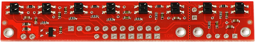
Keep in mind that the QTR line sensor has two 5V pins that are connected to each other! They are identical in function besides being in a different location
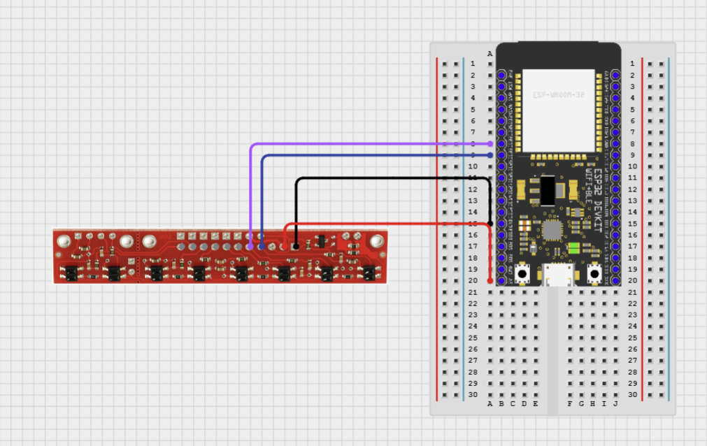
| Line Sensor Pin | ESP32 Pin |
|---|---|
| 5V | 5V |
| GND | GND |
| Signal | Any ADC Capable Pin (i.e. GPIO32, GPIO33) |
If you’re not sure about the ESP32 pinout, then check out this page!
This wiring diagram only shows the situation where two IR/phototransistor pair are used. If you want to use more, simply use more ADC capable pins
Programming
The following program will allow you to continuously read the sensor data from 2 of the photodiode sensors. You will have to calibrate the sensors by positioning the ones you want to use directly over the black electrical tape. If you need to use more than 2 sensors, then you can also move the line sensor back and forth over the black electrical tape to calibrate it.
After the calibration process, you should see the values in the terminal change as you shift the sensors over the black tape.
#include "sdkconfig.h"
#include <Arduino.h>

#include <QTRSensors.h>

QTRSensors qtr;
uint16_t sensors[2];

void setup() {
    // set up Serial Communication and sensor pins
    Serial.begin(115200);
    qtr.setTypeAnalog(); // or setTypeAnalog()
    qtr.setSensorPins((const uint8_t[]) {32, 33}, 2); // pin numbers go in the curly brackets {}, and number of sensors in use goes after

    // calibration sequence
    for (uint8_t i = 0; i < 250; i++) {
        Console.printf("calibrating %d/250\n", i); // 250 is the number of calibrations recommended by manufacturer
        qtr.calibrate();
        delay(20);
    }
}

void loop() {
    qtr.readLineBlack(sensors); // Get calibrated sensor values returned into sensors[]
    Console.printf("S1: %d S2: %d\n", sensors[0], sensors[1]);
    delay(250);
}
TIP: Always calibrate your line sensor to ensure consistent and accurate results.
Extensions
- You received values from the sensor, but what do they mean?
- How does the position value change as you place your line beneath different sensors, and how can you control that?
- What do you do with your robot when you detect a change?
- Consistency in data collection is key for calibration
- Can you automate the calibration process?
- Can you use the super secret NVS functions to save and restore calibration?