Actuators
The word “actuators” is just a fancy word for “devices that create motion,” which can include anything ranging from hydraulic pistons to motors. In our case, electric motors will be the key to your robot’s motion! In this competition, you will be dealing with DC brushed motors and servo motors.
DC Motors
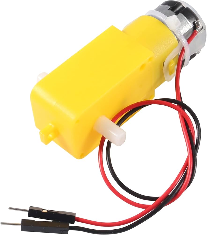
You will be using DC (direct current) motors as the primary means of moving your robot around.
DC motors operate on electromagnetic principles. Inside the motor, there are permanent magnets (stator) that create a stationary magnetic field, and wire coils (rotor/armature) that carry electrical current. When current flows through the rotor windings in the presence of the magnetic field, electromagnetic forces cause the rotor to spin. A commutator and brushes automatically switch the current direction in the windings as the motor rotates, ensuring continuous rotation.
The motor’s speed depends on the applied voltage; higher voltage makes the motor spin faster. The torque (rotational force) depends on the current; more current allows the motor to push harder, such as when moving a heavier robot. Motor speed is controlled by pulse-width modulation (PWM), which is when the supply voltage is switched on and off rapidly. By adjusting the ratio of “on” to “off” time, you can smoothly control the average voltage the motor receives. Direction is reversed by by switching the voltage polarity.
However, directly connecting a DC motor to the ESP32 is not desirable due to lack of direction control and higher voltage/current requirements of the motor. This is where motor controllers come into play.
Motor Controllers
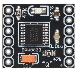
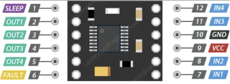
A motor controller, such as the DRV8833, acts as an intermediary between the microcontroller and the DC motor. It allows the microcontroller to control the motor’s speed and direction without directly handling the high current. The motor controller has an H-bridge circuit, which allows different combinations of IN1 and IN2 to change the motor direction.
The following information is an adapted version of this guide.
How to Use Motor and Motor Controller?
Portable Battery Pack Power
First we will go over using an external power source for the ESP32. For this competition, you will be able to control your robot with a wireless game controller to navigate around the field (sensor challenges should be completed autonomously). It would be impractical to power your ESP32 through the on-board USB on the field, so you will use a portable battery pack. This battery pack will be connected using a USB-C 5V breakout board, which ensures the pack provides a steady 5V supply for your ESP32 and motor controller.
To safely power your ESP32 from the battery pack and still have the option to connect it to your laptop to use the serial monitor for debugging, add a diode between the breadboard’s power line and the ESP32’s 5V pin. The diode works like a one-way valve, so it prevents current from accidentally flowing back into your computer or battery pack. Without the diode, you could risk frying your equipment!
Here is a diagram of how your circuit should look:
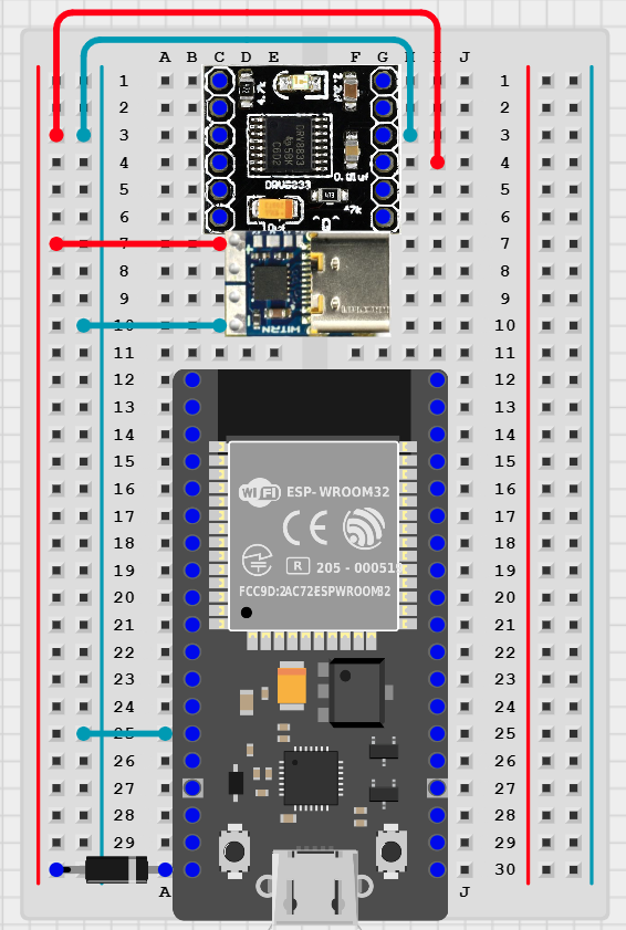
With this wiring, you can safely use both the battery pack and the USB connection!
ALWAYS use a diode on the ESP32’s 5V line when powering it from a battery pack.
This prevents current from flowing back into your computer or battery pack if USB is also connected.
To control a DC motor using the ESP32, a motor controller, and battery pack (WITH or WITHOUT USB CONNECTION), you can connect them together as shown below:
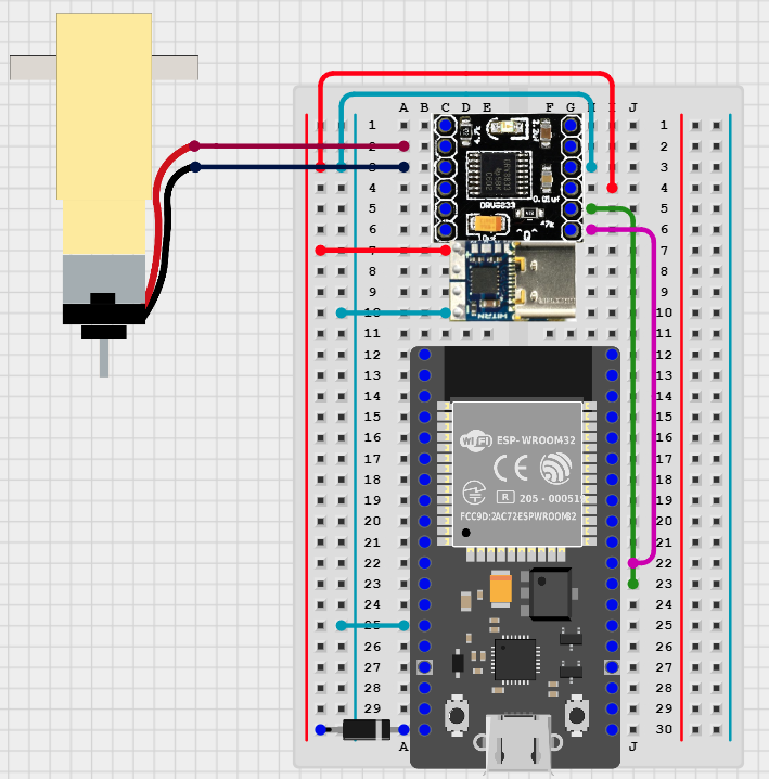
- Note that the wire polarity on the motor does not matter because DC motors’ spin direction is based on the direction of current flowing through them. This direction is controlled by the H-bridge motor driver.
| Motor Controller Terminal | ESP32 Pin |
|---|---|
| VCC | 5V |
| IN1 | Any PWM enabled pin |
| IN2 | Any PWM enabled pin |
If you’re not sure about the ESP32 pinout, then check out this page!
The following is an example of configuring and running the motor in software:
#include "sdkconfig.h"
#include <Arduino.h>

#define IN1  16  // Control pin 1
#define IN2  17  // Control pin 2

void setup() {
  Serial.begin(115200);
  pinMode(IN1, OUTPUT);
  pinMode(IN2, OUTPUT);
}

void loop() {
  // Spin motor
  analogWrite(IN1, 255);  // PWM signal
  digitalWrite(IN2, LOW); // Direction control

  delay(1000);  // Run for 1 second

  // Stop motor
  digitalWrite(IN1, LOW);
  digitalWrite(IN2, LOW);

  delay(1000); // Stop for 1 second

  vTaskDelay(1); // Yield CPU to not starve other ESP32 processes and cause WDT reset
}
Again, more detailed information about the DRV8833 motor controllers can be found here!
Servo Motors
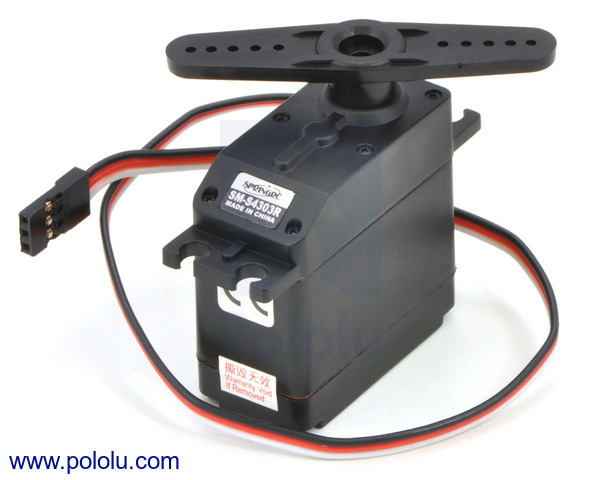
What Are Servos?
Servos are motors that are designed for precise position control. Instead of freely rotating when powered, servos listen to a control signal (usually PWM) to determine where to rotate. Some servos rotate continuously, while others rotate with a fixed angle range (like ours). More advanced servos have other ways to be even more precise such as a feedback system on top of the control signal, but that is not necessary for this competition.
How to Use Servos?
For the servos in our competition, you can use it to precisely control your mechanism for the Mechanical Challenge. To interface it with your ESP32, you will connect the wires as follows:
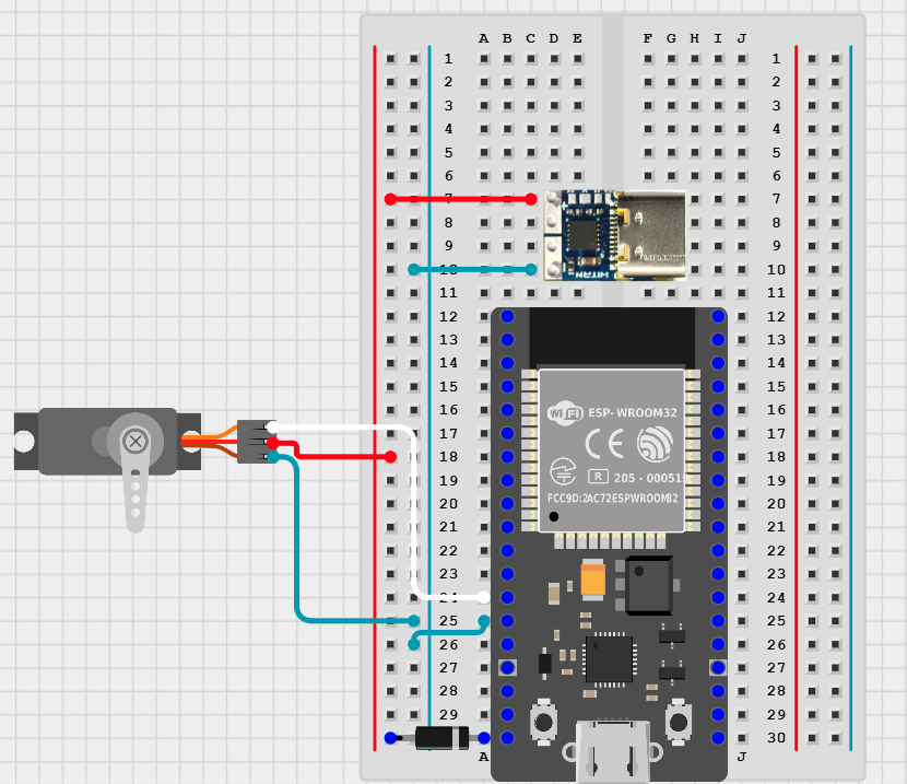
| Servo Wire | Connection |
|---|---|
| Red | 5V from the battery pack |
| Black | GND |
| White | Any PWM enabled pin on the ESP32 |
If you’re not sure about the ESP32 pinout, then check out this page!
In this competition, we will be using the Arduino servo library to control the servos. The following is an example of how to spin a servo using the ESP32’s pin 12 as the PWM output.
#include "sdkconfig.h"
#include <Arduino.h>

#include <ESP32Servo.h>

Servo myServo;

void setup() {
  myServo.attach(12);
}

void loop() {
  myServo.write(0); // Rotate to 0 degrees
  delay(1000); // Delay 1000 ms
  myServo.write(180); // Rotate to 180 degrees
  delay(1000);

  vTaskDelay(1); // Yield CPU to not starve other ESP32 processes and cause WDT reset
}
Simply input a different value in the write() function to change how the servo behaves!